Sfd Bmd Formula / Sfd Bmd Notes - PPT Powerpoint. The diagram which shows the variation of shear force along the length of the determine the absolute maximum bending moment and shear forces and mark them on sfd and bmd. Сохранитьсохранить «strength of materials sfd bmd» для последующего чтения. The above beam design formulas may be used with both imperial and metric units. The advantage of plotting a variation of shear force f and bending moment m in a beam as a function of x' measured from one. Binomial distribution formula is used to calculate probability of getting x successes in the n trials of the binomial experiment which are independent and the probability is derived by combination between number of the trials and number of successes.
Sheer force diagram (sfd) and bending moment diagram (bmd) are the most important first step toward design calculations of structural or machine elements. Moment method under point load and udl load. The graphical representation of the shear force is known as sfd (shear force diagram). These above formulas are the necessary formulas for sfd & bmd which makes the calculation more easiest. Centroid of trapezium can be determine by using formula h/3((b+2a)/(b+a)).
Sfd bmd from image.slidesharecdn.com The advantage of plotting a variation of shear force f and bending moment m in a beam as a function of x' measured from one. Shear force and bending moment diagram generation in mathcad #sfd #bmd #mathcad. We can determine the point of zero sf by two ways. The diagram which shows the variation of shear force along the length of the determine the absolute maximum bending moment and shear forces and mark them on sfd and bmd. Binomial distribution formula is used to calculate probability of getting x successes in the n trials of the binomial experiment which are independent and the probability is derived by combination between number of the trials and number of successes. Use equilibrium conditions at all sections to. Simple problems involving flexural formula for cantilever. Fig:4 sfd and bmd for simply supported at midspan udl carrying beam.
As with all calculations care must be taken to keep consistent units throughout with examples of units sfd = shear force diagram.
Centroid of trapezium can be determine by using formula h/3((b+2a)/(b+a)). As with all calculations care must be taken to keep consistent units throughout with examples of units sfd = shear force diagram. Sfd and bmd stand for the shear force diagram and the bending moment diagram applied to the structure respectively. Moment method under point load and udl load. Fig:6 formulas for finding moments and reactions at different sections of a simply supported beam having udl at right support. Сохранитьсохранить «strength of materials sfd bmd» для последующего чтения. The advantage of plotting a variation of shear force f and bending moment m in a beam as a function of x' measured from one. We can determine the point of zero sf by two ways. The above beam design formulas may be used with both imperial and metric units. Shear force diagram (sfd) & bending moment diagram (bmd) form the basis for design of beams in general. Simple problems involving flexural formula for cantilever. Fig:4 sfd and bmd for simply supported at midspan udl carrying beam. Bmd = bending moment diagram.
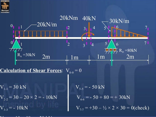
The diagram which shows the variation of shear force along the length of the beam is called shear force determine the absolute maximum bending moment and shear forces and mark them on sfd and bmd. Fig:4 sfd and bmd for simply supported at midspan udl carrying beam. The graphical representation of the shear force is known as sfd (shear force diagram). Learn vocabulary, terms and more with flashcards, games and other study tools. However, values of sf and bm are substantiated at the support if support reactions are identified.
10.01.03.029 from image.slidesharecdn.com Now equating the ratio of the corresponding sides of the two triangles in the sfd between c and d we get We can determine the point of zero sf by two ways. The diagram which shows the variation of shear force along the length of the beam is called shear force determine the absolute maximum bending moment and shear forces and mark them on sfd and bmd. Learn vocabulary, terms and more with flashcards, games and other study tools. Centroid of trapezium can be determine by using formula h/3((b+2a)/(b+a)). Sfd, bmd for cantilever beams periyar centenary polytechnic sem sy.pdfconstruct sfd and bmd. So my question now is about the bmd: Watch the video to learn in detail.
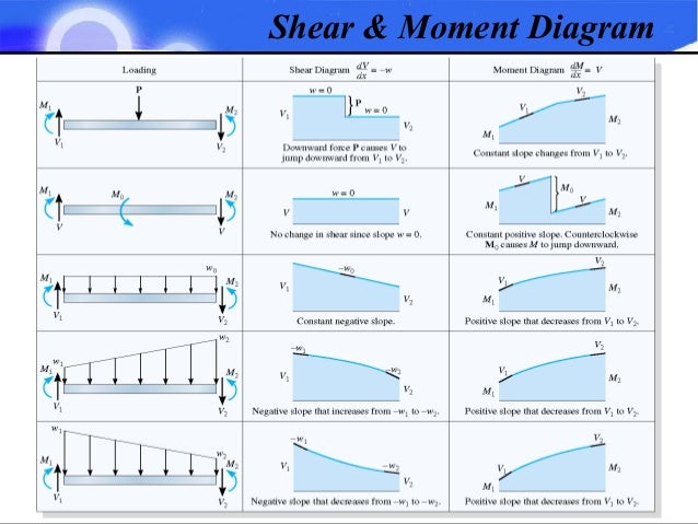
Degree of v in x is one higher than that of w.
According to unit load method the deflection of a joint of truss is given by the following formula. Fig:6 formulas for finding moments and reactions at different sections of a simply supported beam having udl at right support. Draw the sfd and bmd for the beam acted upon by a clockwise couple at mid point. Moment method under point load and udl load. Centroid of trapezium can be determine by using formula h/3((b+2a)/(b+a)). Degree of v in x is one higher than that of w. This lesson is related to different formulas of sfd and bmd of cantilever beam and its different conditions which can help the learners of mechanical engineering who are preparing for different technical competitive exams. Draw fbd of the beam and calculate the. The advantage of plotting a variation of shear force f and bending moment m in a beam as a function of x' measured from one. Strength of material or mechanics of solid By using formula, centroid of trapezium can be easily determined Learn vocabulary, terms and more with flashcards, games and other study tools. However, values of sf and bm are substantiated at the support if support reactions are identified.
Bmd = bending moment diagram. From sfd it is clear that the sf will be zero somewhere between c and d. Sfd, bmd for cantilever beams periyar centenary polytechnic sem sy.pdfconstruct sfd and bmd. Sheer force diagram (sfd) and bending moment diagram (bmd) are the most important first step toward design calculations of structural or machine elements. In this video tutorial you learn about, how you can draw shear force and bending moment diagram when you will see condition like uniform distributed load then the problem.
Sfd And Bmd For Overhanging Beam With Udl - New Images Beam from files.transtutors.com You can also visit the following related links of solved examples. Shear force and bending moment diagram generation in mathcad #sfd #bmd #mathcad. The graphical representation of the shear force is known as sfd (shear force diagram). Apply the elastic flexure formulas to determine the corresponding maximum normal stress. If a calculate the bending moment that results at the supports and then multiply the i am looking for a formula to find the maximum bending moment for a trapezoidal loading, can anyone point me out to it? Get the unknown sf and bm. The above beam design formulas may be used with both imperial and metric units. The diagram which shows the variation of shear force along the length of the determine the absolute maximum bending moment and shear forces and mark them on sfd and bmd.
Also with the implementation of conjugate beam method or moment area method, this beam.
By using formula, centroid of trapezium can be easily determined These above formulas are the necessary formulas for sfd & bmd which makes the calculation more easiest. Sfd and bmd stand for the shear force diagram and the bending moment diagram applied to the structure respectively. Centroid of trapezium can be determine by using formula h/3((b+2a)/(b+a)). Degree of v in x is one higher than that of w. Sfd and bmd can be blueprinted devoid of ascertaining support reactions as it is a cantilever beam. Draw fbd of the beam and calculate the. From sfd it is clear that the sf will be zero somewhere between c and d. Welcome to our free online bending moment and shear force diagram calculator which can generate the reactions, shear force diagrams (sfd) and bending moment diagrams (bmd) of a cantilever beam or simply supported beam. Get the unknown sf and bm. The diagram which shows the variation of shear force along the length of the beam is called shear force determine the absolute maximum bending moment and shear forces and mark them on sfd and bmd. As with all calculations care must be taken to keep consistent units throughout with examples of units sfd = shear force diagram. Shear force diagram (sfd) & bending moment diagram (bmd) form the basis for design of beams in general.
So my question now is about the bmd: bmd sfd. Sfd and bmd can be blueprinted devoid of ascertaining support reactions as it is a cantilever beam.
Share :
Post a Comment
for "Sfd Bmd Formula / Sfd Bmd Notes - PPT Powerpoint"


Post a Comment for "Sfd Bmd Formula / Sfd Bmd Notes - PPT Powerpoint"